

It’s no secret I’m a huge proponent of using as many factory parts as is feasible when building most performance engines, and there is no better example of how well factory parts can perform than the F.A.S.T. series. While I am not in any position to build and try to campaign a car in the series, I’ve had a nagging desire for some time now to try my hand at a F.A.S.T.-style engine. Along the same lines, I’ve always wanted to build a serious effort high-rpm screamer small block Chevy, and before I knew it the two ideas began to blend into one, which brought me to the project you see here. So think of this build as “F.A.S.T.-flavored”, but I’m coloring just slightly outside the lines on a few minor (peripheral) details for now.
While I am a firm believer in good old-fashioned cubic inches, as the saying goes, “there’s more than one way to skin a cat.” (no offense to any cat lovers who might be reading)
Brute torque is one way to get from point “A” to “B” in as little time as possible, but a butt-load of rpm and a big gear in the rear differential can work equally as well…if not better at times! With that in mind said, I decided to stray from the beaten path of mega-cubes and obnoxious torque figures and instead reach for the moon…or at least the high side of the tach scale.
Two rules about racing engines:
1) An engine is little more than a glorified air pump
2) RPM = horsepower
Since an engine is really nothing more than a glorified air pump, the first step in making power is getting in as much air/fuel as you can. The second step is to squeeze it as tightly as the combination will allow. The third step burn it as efficiently as possible. The last step is to get the spent mixture out of the engine as efficiently as possible.
Here’s my angle: the first three steps aren’t too much of a challenge for a large displacement engine, but the fourth step becomes an obstacle since these engines are hindered by their restrictive factory exhaust manifolds. In other words, getting the air/fuel in isn’t the challenge, it’s getting it back out, which is exacerbated exponentially as RPM climbs. My theory is, a smaller cubic inch engine should be able to carry the power further up in the rpm range than the larger engine before the exhaust pumping losses become the primary source of restriction.
A little math:
Horsepower is merely a mathematical calculation of torque multiplied by rpm then divided by a constant, 5252. In other words, an engine that makes 400 ft.lbs of torque at 6000 rpm is making 457 HP at the same 6000 rpm. However, if the engine can carry that same 400 ft.lbs of torque up to 8000 rpm, that 400 ft.lbs now calculates out to 609 horsepower.
Another thing to consider is that the rear axle ratio multiplies the torque as well. The engine making 400 ft.lbs @ 6000 will typically only use a low-mid 4 series gear, where the engine that makes 400 ft.lbs @ 8000 rpm can use a 5+ gear set. So how does that make a difference? By multiplying the available torque by the rear axle ratio, you can derive a "total torque" figure that is being applied to the rear tires.
The following is admittedly somewhat simplified for the sake of clarity.
400 ft.lbs (@ 6000 rpm, or 457 HP) X a 4.10 gear set equates to 1,640 ft.lbs of torque being applied.
400 ft.lbs (@ 8000 rpm, or 609 HP) X a 5.38 gear set equates to 2,152 ft.lbs of torque being applied.
All other things being equal, which do you think should accelerate down the track quicker?
All the above finally brings me back full-circle so the following details will (hopefully) now make sense.
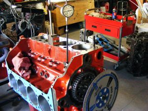
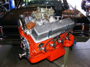
The engine is 306″ and is being patterned after a 1967 Z28. Why a `67 Z? Because I dig `em.
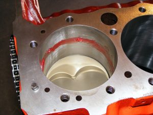
The block is an “010” 350 4-bolt block which has been fitted with main studs, line honed, bored & honed with torque plates and decked to put the pistons down .010″ in the hole.
The crank is an early small journal 283 steel crank which has been cut .010″-.010″.
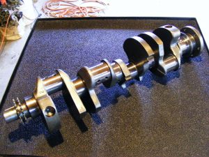
Some may catch an apparent snafu there, specifically the fact that the 283 main bearing journals are smaller than those on a 350, which appears to make stuffing a 283 crank into a 350 block impossible. Luckily, there are two methods to address this. There are special extra-thick main bearings available from Clevite which allow a bolt-in installation. There is one problem with this though, they are only available down to a .010″ under size. If the crank ever needs to be cut again, you’re s.o.l.
The other method is to use a main bearing “spacer” which will receive standard 283 small journal main bearing inserts, which are available in a plethora of sizes and configurations. While I initially planned to use the Clevite thick bearings, I later decided to utilize the spacer inserts instead in order to provide myself with more bearing options later down the road with the engine.
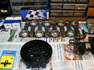
The rods are Scat small journal pieces which measure in at 6.125″ long (sorry for the B&W photo, it’s all I had @ the moment).

I went with these longer rods for several reasons;
1) Longer rods = shorter (and lighter) pistons
2) Longer rods can help an engine “hang on” past peak Horsepower RPM w/o falling off as rapidly as a shorter rod.
3) There just happened to be a shelf piston available to make this combination work, negating the need to drop big $$$ on a set of custom pistons. This is also a plus in the event that replacement pistons are needed–they’re available from most any speed shop in singles instead of having to purchase a minimum order of 4+ for a replacement custom unit.
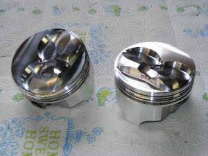
The pistons are KB forgings which are designed to be used in a 327 with a 6″ connecting rod. Conveniently enough, the stroke difference between the 302 and 327 just happens to be .250″, which means a readily available 6.125″ rod splits the difference and allows these 327 pistons to work in a 302.
The rings are a custom 1/16 1/16 3/16 set provided by Total Seal. I really don’t want to get into certain specifics of the build, and the ring package is one thing I’m keeping under my hat.
Same thing goes for the camshaft as well, but I can divulge that it’s a Bullet roller, and it’s pretty friggin’ big.
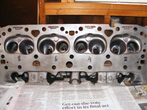
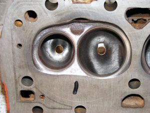
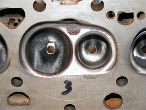
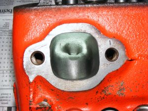
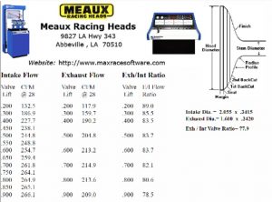
The heads are a pair of “462” double hump castings that were originally worked over by one of the best cylinder head guys in the country, Dave Layer (RIP) of “Heads Up!” cylinder heads. The heads were not “maxed out”, I wanted to see what we could achieve with them w/o digging way down deep into Dave’s secret bag of magic tricks.

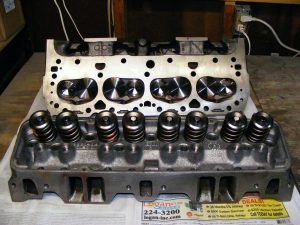
They were later worked on further though by another shop, but more details on that later.
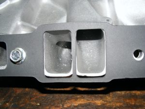
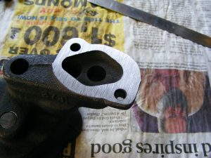
The intake is a factory `67 Z unit I picked up on the yenko.net forums. Dave put the mojo on the intake as well.


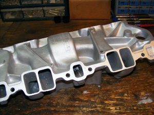

Before anyone strokes out over carving up this fairly valuable intake, take note that it had led a pretty hard life and has had numerous weld repairs over the years, as well as a previous half-assed attempt at port matching. This caused Dave a little grief. The heads are cut out to FelPro 1205 gasket dimensions, and when Dave went to fix the previous attempt at port matching, there wasn’t enough meat left to work with. As such, the runners were fitted a little more closely to a FelPro 1206 gasket. However, there isn’t enough material at the top of the manifold runners to go all the way out to a 1206.
1205 gasket alignment:
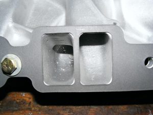
BARELY enough coverage to seal:
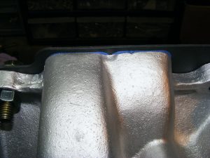
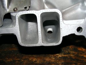
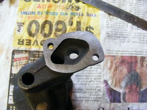
1206 gasket alignment—or mis-alignment:

Gasket slid down to the bottom of the bolt holes:
Gasket slid up to the top of the bolt holes:
That’s obviously not going to work:

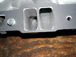
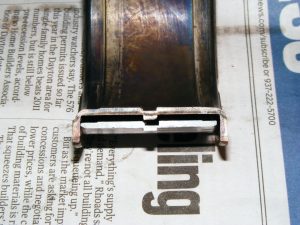
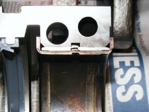
An old racers trick to help hold the gaskets in place when there isn’t much meat to seal to the runners:
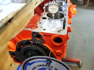
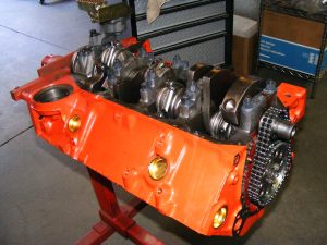
So there’s the basics on the build. Next it was time for initial mock-up;
The first issue reared its head right off the bat–the locating tang slots on the spacer shells weren’t cut correctly which caused interference with the locating tangs on the actual bearings themselves:
Some careful filing alleviated the interference.
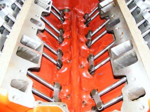
The cam was installed in the block, the bearings were lubed and the crank was installed, and the #1 rod & piston were installed so the cam could be degreed in:
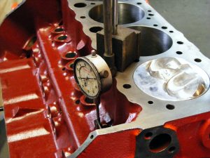
Next, a cylinder head was installed so pushrod length could be measured and valve to piston clearance could be checked. You’ll notice this engine is equipped with a set of T&D offset shaft rockers (1.6 intake ratio, 1.5 exhaust). The reasoning for this was the anticipation of widening the intake ports out past the pushrod pinch which would require both brazing/welding the heads and the use of said offset shaft rockers (and offset roller lifters–more on that shortly) for clearance. As it was, the initial cut for pushrod clearance was nowhere near adequate. (*note*-these heads have been angle milled with further exacerbates the interference issue)
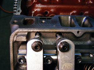


The interference was so bad the pushrods couldn’t even fully seat in the cups on the rockers (and these were only 5/16″ checking pushrods):

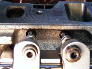
Back to the machine shop to machine the pushrod holes out further.
With the pushrod holes in the heads were now providing ample room, mock-up proceeded again–one problem resolved.
But…there’s always a “but”, isn’t there?
The initial mock up was with the timing set installed straight up–I hadn’t attempted to degree in the camshaft yet.
Next, I *attempted* to degree in the camshaft. It went something like this;
Timing set installed straight up, verify TDC, check. Move dial indicator over to the lifter, check ICL, the ICL comes in about 3.5° late. No big deal, right?…the timing set has multiple crankshaft keyways just for this sort’a thing, we’ll just scooch the cam ahead 4° and see what that does.
Pop the crank gear off, move it to the +4° keyway, put the timing set back on, re-check TDC, move the dial indicator over to the lifter, check ICL…wait..what?….now it’s 4° advanced??…
Re-check TDC–spot on. Move the dial indicator over to the lifter again, re-check ICL, still coming up 4° advanced.
Hmmm…I must’a mis-read the numbers when the timing set was installed straight up. Let’s start over again and see what we get…
Pop the timing set back off, move the crank gear back to straight up, put the timing set back on, re-check TDC, good to go. Move dial indicator back over to the lifter, re-check, AGAIN, ICL is late by 3.5°!
Re-set the set back to +4 again, and AGAIN it’s now 4° advanced!
Just out of morbid curiosity, I pop the gears off again and this time install them at the 4° retarded setting…go through the whole spiel re-setting everything again…
…any guesses where it came in THIS time??
How’sabout almost 10° retarded!
So to boil it down, the “straight up” setting on the timing set put the cam in at 3.5° late, the “+4” setting advanced the cam a total of 8°, and the -4° setting put the cam in 5.5° late.
I won’t mention the brand name of the initial timing set, but suffice it to say it went back and a Crane Billet set was ordered in to replace it.
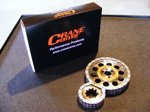
Since the previous attempt indicated the cam needed to be advanced, I initially installed the new Crane timing set at the +4° setting to start.
A quick check @ .050″ on the degree wheel indicated the cam was now 8° advanced!
For reference, the recommended ICL on the cam card = 103°. +4° on the Crane set =95.5° ICL
A quick refresher so you won’t have to keep scrolling up to compare numbers:
Old timing set:
“Straight up” (0) = ICL about 3.5° late, or 106.5°
+4° = ICL 4° advanced, or ~99°
-4° = ICL 6.5° retarded, or 109.5°
OK, back to the Crane set. Since +4° put the cam in @ 95.5°, I moved the set to straight up. That put the ICL at 99.75°. Getting there, let’s see what -4° does…re-set TDC, move the dial indicator over to the cam, quick check of the .050″ #’s and everything’s looking good, roll it over to measure the ICL, and BINGO, comes in at 103.75°! All 4 settings I measured on the Crane set were within .5° of perfect!
In case I haven’t mentioned lately, Crane Cams ROCKS!
SO!…now that I’d gotten that outt’a the way, it was time to check valve to piston clearance again. Only one problem…there IS none!
I set the lash at 0, gently try to roll the engine one revolution, make it about 3/4 of a turn and it stops dead in its tracks. No sweat, I was expecting that. I knew the intake side hit previously, so I set the intake rocker at .022″ (recommended) lash and give it another attempt.
This time it makes it all the way around. OK, we’ve got clearance now, but how much?
I did the old tried & true clay method and it locked up tight again, so I had to check v/p clearance the tedious way–1° at a time using the dial indicator to plot the v/p clearance curve. I started at 10°BTDC and had .128″ clearance. Not bad, right?
by 5° BTDC it was down to .087″, and by TDC it was down to .045″. It wasn’t done yet though!…by 5° ATDC it was down to .019″, and from 9° through 18° ATDC, the actual measured clearance was zero on the dial indicator! It had just enough room to turn, and that was it. It didn’t get back to +.050″ until 30° ATDC, and by 35 ATDC it finally made it back to .100″ clearance.
I also plotted the exhaust side, and with zero lash it was closest at 11° BTDC with .072″ clearance. It only took a little kiss to provide exhaust valve clearance, but those intake pockets took a whack. I sent the pistons out to Eric @ Rebco machine and had him fly cut the domes as well as radius all the sharp edges, add lateral gas ports, and then apply a thermal barrier coating to the domes. This was done as I planned to lean on the tune hard, and I wanted a little extra insurance in case I pushed it a little too far. Once the pistons returned it was time to begin assembly.
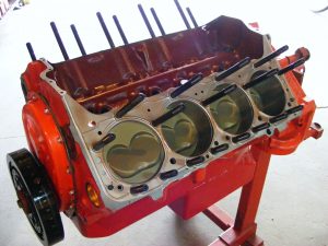
Here’s what I started with:
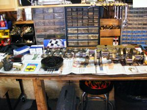

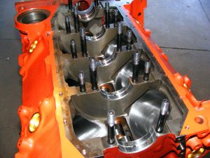
Once everything had been laid out and again cleaned within an inch of its life, the final assembly began. The cam was oiled and installed in the block, and the main bearing spacers were set in place.
The main bearings were installed in the block and the caps were torqued to spec so bearing clearances could be measured.
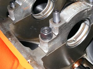
Here’s a quick note regarding main studs;
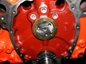
In the pic below, note how the top of the stud is actually sitting slightly below the top threads of the nut. This is not the correct way to install the studs–the top of the stud must protrude at least 1 thread above the nut to ensure full thread engagement. This is resolved by simply backing the stud out of the hole a turn or so until there is one thread showing above the nut once tightened.
Below-incorrect:
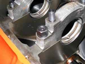
Below-correct:
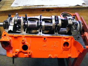
Once all the rod & main bearing clearances had been verified, the main bearings were lubed and the crank was set in place. The thrust was re-measured (turning the crank to check thrust in several spots) with the new main bearing set and checked in at a perfect .008″ clearance.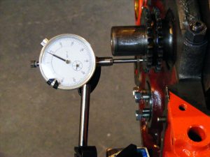
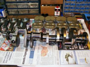
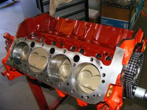
Rather than boring you with a bunch of pictures of me assembling the rods and pistons, suffice it to say the engine was soon an assembled short block.

I did run into one other snafu during assembly; Here’s the mounting surface on my brand new (and rather expensive) racing oil pump. Notice how it’s not machined flat? I noticed it as well, and it was bad enough that the pump actually rocked on the rear main cap. I disassembled the pump and gave it a quick surfacing.

Lastly, I lapped the casting on a surface plate using a piece of 220 grit sandpaper and machining oil. It took a while, but it’s flat now!
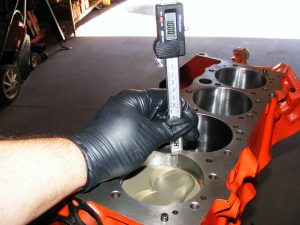
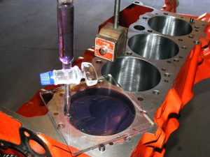
The next thing on the list was to measure the actual dome volume so the compression ratio could be calculated.
Next up on the list was to c.c. the heads and get the spark plugs indexed. First up was the plugs. Because of the heavy angle milling on these heads and the fairly substantial dome on the pistons, the plugs in this engine must be indexed to keep the domes from hitting the ground straps. Along the same lines, a projected tip plug can not be used here either as it will also cause an interference issue with the dome. Washers of varying thicknesses are used to properly orient the ground straps.
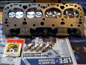
Witness lines were drawn on the plugs to correspond with the location of the ground straps. This makes it easier to index the plugs when the engine is assembled.
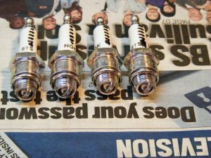
The plugs in the first two chambers indexed fine without having to use any indexing washers.

The next two chambers didn’t line up and required the use of washers to get the plugs indexed.

Properly indexed.
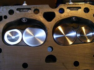
Next up was to c.c. the chambers:

Less than 1/2 c.c. different than what Dave said he measured them at, which ain’t bad considering my equipment isn’t anywhere near as precise as Dave’s is.

Final compression ratio: 13.09-1.
Since that was all outt’a the way now, it was time to re-clean everything again (noticing a pattern here???…) so I could sauce up the head studs with Permatex Teflon thread sealant and hit the Fel-Pro steel shim head gaskets with some copper coat.
The timing cover is a Milodon unit with a reinforcement in the center for use with a cam thrust button–a must when using a roller cam, and this engine is equipped with a Crane button (big surprise there, eh? lol). Cam end-play is ~.010″. The oil pan is an 8 quart Hamburger unit complete with a built-in windage tray and scraper. This pan should provide ample oil & windage control for this engine.
Next, the cylinder heads went down and were torqued in place. The rockers and stands were mocked up again for the umpteenth time to set end-to-end adjustment on the stand to center the rocker tips over the valve stems. Once the stands were properly centered, the fasteners were removed one at a time and Permatex Teflon sealant was applied to the threads, then the fasteners were reinstalled and torqued to spec.

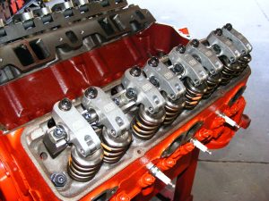

Next, the pushrods were installed.

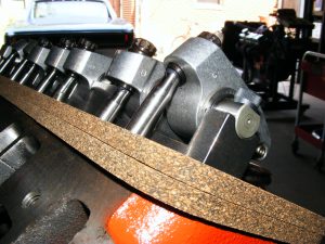
For pushrods, I went with Trend Performance components. These units measure in at 8.075″ long. Also to note, these pushrods are equipped with 210° tips as opposed to the more conventional 180° tips. This engine needed the 210° ends on the pushrods; note the severity of the angle here @ close to full lift–a regular 180° end pushrod could actually bind at the edges of the adjuster cup on the rocker arm. The extra 30° of radius gives everything enough room to move.
When installing a rocker arm system such as this T&D unit, there are a number of details that must be checked and verified before any assembly can begin. Pushrod length measurement is critical with this rocker arm system as the adjuster nuts only have a 2 turn range of adjustment.
These rockers must be “base line” adjusted before measuring for pushrods. To do so, you loosen the lock nut and turn the adjuster screw counter-clockwise until it tops out it’s range of adjustment. You then turn the adjuster clockwise one full turn–this is the nominal setting. You then install the adjustable pushrod and take your measurements. There is one other thing to address–I take the pushrod measurement with a feeler gauge set to lash spec installed since this is what the engine will actually see in operation. Not only that, but 1/2 turn on the adjuster nut is roughly equivalent to .025″ @ the tip of the rocker, which doesn’t leave much wiggle room for error, or even for lash changes.
Also, since this engine uses offset lifters, it is imperative to verify the lifters are installed in their correct locations–there are 8 center cup lifters for the exhausts, 4 left offset and 4 right offset for the intake sides. You also need to verify the rocker arms are installed in their correct locations and that the pushrods are correctly seated in their respective cups (upper and lower)–it’s not hard to mess this up, and if something’s out of place here, you’re going to quickly wind up with an expensive pile of shrapnel.

Note the doubled up valve cover gaskets: In an effort to remain withing the spirit of the F.A.S.T. rules, I tried to utilize “correct” `67 script valve covers here–although the ones I had were regular painted units as opposed to the correct chromed units found on a `67 Z. Unfortunately there just wasn’t enough room for the shaft rockers with the OE valve covers–resolving this would’ve required sectioning the covers, adding material for additional height, welding the covers back together, then getting them chromed. Since this engine is just a “dyno mule” for now, the OE cover idea was shelved for aftermarket covers.
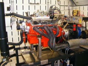
The rest of the build was pretty straightforward. The intake was bolted down with a set of Mr. Gasket intake bolts, the distributor was timed in and it was time to take this lump to the dyno and see what it could do.
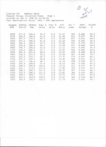
We spent all day on the dyno, making 18 pulls (the first 17 pulls with 1 3/4″ headers to get things dialed in, the last with manifolds), and we went from “oh sh*t&” on the first pull to “holy sh*t!” on the (next to the last) last pull.
2 things to note:
1) The cam is off a bit–
……A) I wanted peak power @ 8000+, it peaked at ~7600 and was down ~15HP @8000.
……B) This cam did NOT like the manifolds at all. We definitely need to take another swing at the camshaft.
I got to the dyno shop by ~10:30-ish, we go over the pre-test details. We fire the engine with the Pertronix distributor I bought for this build. The first thing I notice is that this damned thing thumps HARD!…there’s no way that’d pass “F.A.S.T stock-sounding idle” requirements. (FWIW, this was my first clue that the cam wasn’t going to be what I wanted)
The next thing I notice is that it doesn’t want to idle worth a crap, and I knew exactly what the problem was: I didn’t get a chance to lock out the advance curve on the Pertronix distributor, and with the cam in this engine, it mandated a locked timing curve. The dyno guy scurries off and quickly returns with a MSD distributor with a locked-out curve. Groovy.
We swap distributors, light it back up, set the timing at 36°. She’s running my “mule” 3310 Holley on VP C12 fuel for initial testing. We make a soft pull from 3000-5000. The engine sounds labored. A glance at the dyno sheet reveals a mere 324 HP @ 5000 rpm.
Crap, that ain’t good. The air/fuel looks OK and a plug check shows no signs of trouble, so we make another shot from 3000-6000. This time it makes 343 HP @ 6000 and really sounds like crap.
I’m teetering on panic mode right about now, wondering what the hell I missed. This thing should be at least 50+ HP stronger than this. Time for another looksie, we’re obviously missing something.
I bump the engine over to make sure I didn’t screw up the paint mark on the balancer, and out of the corner of my eye I spot something”odd”…the distributor jumped UP each time I bumped the starter! A closer look revealed that the Moroso distributor hold-down bracket wasn’t sitting level on the intake which caused it to cock off to one side when tightened, which subsequently allowed the distributor to move.
One bullet dodged! Another hold-down was quickly procured and we were back in business.
Pull #3 was from 3000-600 again, and this time we were rewarded with 409 HP @ 6000. Not what I was looking for, but still a healthy gain. Another plug check showed a slightly lean condition, so the jets were bumped on all 4 corners.
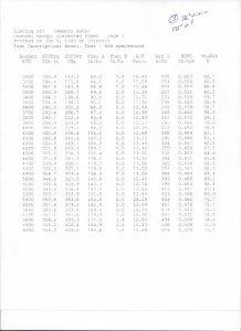
Pull #4 went from 4000-7000. We saw a jump to 443 HP @ 7000. Another plug check showed good color on the plugs, so we left the 3310 alone from that point on.
I decided to run a quick lash check before pull #5. All was well with the lash consistently tight about .002″.
I have to interject this here…those T&D shaft rockers are the bees knees–man those things are nice to work with.
Anyhow, we decided to bump the pull to 7600 and see what was left up top. Pull #5 saw 452 HP @ 7500.
Steadily making progress, and it was noted that she sure sounded good upstairs.
Pull #6 saw a 2° bump in timing to 38°.
466 HP @ 7400 for a 14 HP gain!
For pull #7, the plug gaps were tightened up from .030″ to .025″ just to make sure we weren’t snuffing out the fire up top.
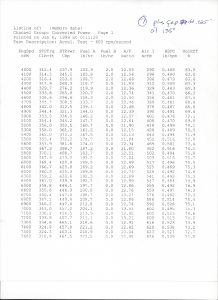
465 HP @ 7300, looking pretty consistent.
For test #8, we decided to swap the old 3310 for a Holley 950 HP carb to see if there was anything to be had with a more modern carb/calibration. Pull #8 was a check-out pull to make sure the fuel curve was OK, which it was. Pull #9 was a full pull from 4000-7500 showing a peak of 464 HP @ 7400.
The 950 picked up 2 HP @ 4000, 2 HP @ 4500, 3.5 HP @ 5000, 15 HP @ 5500, 4 HP @ 6000, was down 6 HP @ 6500, down 3 HP @ 7000, and up 1 HP @ 7500.
Who says the old Holley 3310’s are obsolete designs?!?
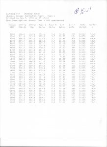
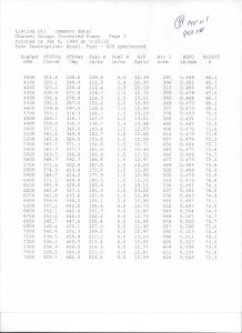
For the 10th pull, we drained the Valvoline VR1 10W30 racing oil and poured in Mobile 1 5W20 full synthetic oil (6 quarts for both fills, 7 quart pan). Oil and water temps were set to the same as pull #9.

The 5W20 was worth 5 HP @ 4000, down 4 HP @ 4500, up 7 HP @ 5000, up .5 HP @ 5500, down 2 HP @ 6000, up 1.3 HP @ 6500, 10.5 HP @ 7000 and down 1.7 HP @ 7500. Peaks were within 1 HP @ 5800 for torque and 1 HP @ 7200-7300 for HP.
For the 11th pull, we bumped the oil up to 150° and the water down to 100°. We had been running the water at ~125° and I wanted to see if there was anything to be had with hotter oil and colder water.
Peak power was up to 473 @ 7200 for a gain of ~8 HP.
For the 12th pull, we bumped the timing up another 2° to 40° total. The plugs were looking OK with the water @ 125° and looked even better at 110°, and the heat line on the ground strap was dead center, so we decided 40° was safe @ 110°.

She definitely liked that, showing a peak of 481 HP @ 7500.
In light of the peak now showing @ 7500, we decided to tempt fate and wind her up to 8000 for the “lucky” 13th pull.
482 HP @ 7300-7400, and down ~14 HP @ 8000. This verified my suspicions that the engine wants a different camshaft, and as I mentioned earlier, that will be in the works later.
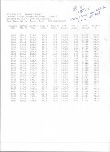
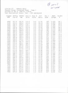
Pull #14 saw a swap from the 3310 to another 780 cfm vacuum secondary carb, a service dated 3910 unit built specifically to utilize VP’s “Q16” oxygenated fuel. As setting a carb up for Q16 fuel was outside my realm of expertise at the time, I enlisted QuickFuel to set this unit up for me. I restored the unit and sent it to them for calibration. The C12 was drained from the dyno fuel cell, and a few gallons of Q16 were poured in.
The 14th pull from 4000-6000 showed everything looked good, so for the 15th pull we took her back up to 7500 again.
497.2 HP @ 7200 rpm!…dang, SO close! Let’s see if we can’t sneak those last few ponies out of hiding!
Pull #16 saw a water temp drop to 95° and a bump to 180° for the oil.
No luck! 495.1 HP @ 7500. Looks like that oil doesn’t want/need to be that hot for peak power.
Let’s take one more swing at it. So far all pulls had been made at a 600 rpm/second acceleration rate. Let’s see if putting a little more load on the engine by dropping that down to 300 rpm/second will help.
Pull #17: 167° oil, 100° water, fingers crossed…..
THERE IT WAS! 504 HP @ 7400 rpm! That was my goal with headers, and once I realized we were off quite a bit on the camshaft I was pretty doubtful we would see it. Again, keep in mind the cam in this engine as supposed to be designed to run with ported exhaust manifolds, and was to have a “stock” idle. The idle went out the window as soon as the engine fired for the first time, and w/o giving away any camshaft details, the LSA on this cam has been a concern to me since I received it, but I was placing my trust in someone else’s expertise. It’s not a big issue, I didn’t expect them to hit a bulls-eye the first time around, that’s all part of the deal when building engines like this.
Now that we’d hit my power goal with the headers, it was time to try the iron exhaust manifolds.
As much as it pains me to say this, as I feared once I realized the cam wasn’t right, the manifold test was a bust. The engine flat-out HATED the manifolds, losing 95 horsepower when they were installed. However, even though the engine was obviously unhappy with the manifolds, peak power still came in @ 7200 rpm. As such, that will have to be re-tested during the next round of testing.
504 HP from 306″ is just under 1.65 HP/CI, and 397 lb.ft of torque is 1.29 lb/CI. That’s pretty stout considering how much there is still left on the table with this build.
This wrapped up the first phase of this project. Shortly afterwards I pulled the heads off and sent them out to be worked over far more extensively. We could’ve gone even further with these heads, but that would’ve required new pistons with bigger domes to regain the lost compression from the chamber modifications, plus it would’ve required epoxy work and/or welding on the heads–which simply was and is not in the budget for this particular project.
I did note two things when the heads came off:
1) The burn pattern on the pistons looks very good.
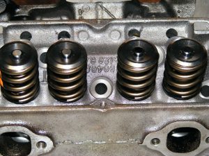
2) It appears the springs may not quite have been up to snuff. The tips of the valves and the valve locks show some minor signs of valve float.
Here are the cylinder heads after the second round of porting:
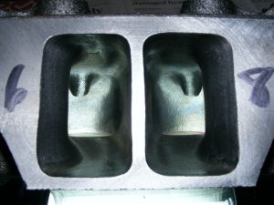
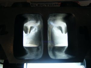
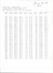
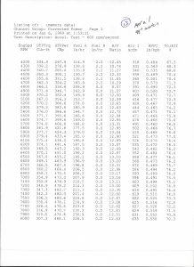
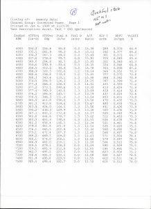
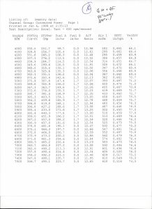
I thought it might be interesting to see the flow numbers between two different benches.
There were no modifications done to the heads in between tests:
________Bench 1__________________Bench 2__________Difference +/-
Lift——-Intake——Exhaust————–Intake—–Exhaust—-I——E—–
.200——-128.2——-111.5—————-124.6——117.0—–(-3.6)- (+5.5)
.300——-179.2——-142.6—————-168.5——150.1—–(-10.7)-(+7.5)
.400——-213.6——-161.9—————-203.0——166.4—–(-10.6)-(+4.5)
.500——-223.4——-172.9—————-222.7——173.5—–(-0.7)–(+0.6)
.600——-225.4——-180.1—————-216.0——177.7—–(-9.4)–(-2.4)
.700——-229.6——-185.2—————-218.8——177.2—–(-10.8)-(-8.0)
.800——-231.8——-186.9—————-218.8——177.7—–(-13.0)-(-9.2)
Just like a dyno, no two flow benches are exactly alike.
Note that bench 1 used a 4.06 bore adapter and no pipe on the exhaust and bench 2 used a 4.03 bore adapter and no pipe on the exhaust for the above numbers, but with a pipe on the exhaust flowed 194.4 cfm @ .700 lift.
Some of the difference in flow #’s is certainly attributable to the difference in bore adapters…how much?…I don’t know, but it’s not a large amount.
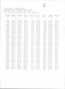
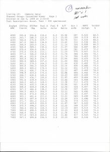
Final flow sheet:
Two new “header” cams are ready for testing and another cam specifically ground for use with the exhaust manifolds is also waiting in the wings. Due to time & budget constraints, the next round of dyno testing will likely only be an evaluation of the new porting and probably the intake manifold tests. The camshaft and exhaust manifold/cam test will have to be done later. However, to facilitate the eventual cam swaps AND to allow moving the cams +/- in the engine now is a Jesel belt drive system I managed to score locally.
The intakes waiting to be tested are a Holley Strip Dominator single plane unit, and an Offenhauser version of GM’s legendary Crossram intake along with a pair of true crossram Holley LIST 4295 carbs.
Original “610” Z28 intake:
Holley Strip Dominator intake:

Offy Crossram intake:
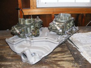
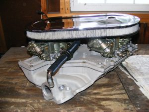


Note that the Offy intake took quite a bit of work just to get it onto the engine, but I’ll go over that at a later time. Stay tuned for the next round of testing!