

Installing and adjusting your Holley carburetor:
GM divorced choke style with external float adjustment
To print a copy of this article or save a copy for reference please click on this link: Holley Tuning PDF.
After confirming the carburetor mounting surface is clean, place the appropriate carburetor base gasket(s) in place on the manifold, then install the carburetor.
*DO NOT OVERTIGHTEN THE CARBURETOR MOUNTING FASTENERS*
Check your repair manual for the appropriate fastener torque setting. Typical 5/16″ carburetor fasteners require 60-80 inch/lbs (approx. 5 to 6.6 ft/lbs). Over-tightening can cause damage to the carburetor throttle body.
Install all peripheral vacuum and fuel lines, and and baseline adjust all choke linkage(s). Again, check your repair manual for appropriate hose and line routing as well as choke settings for your particular make/model of vehicle. Before attempting to start the engine, operate the choke and throttle linkages by hand to ensure their proper operation and to check for any potential binding or other interference issues.
*ALWAYS HAVE AN APPROPRIATE FIRE EXTINGUISHER HANDY WHEN FIRST STARTING A NEW CARBURETOR*
Crank the engine for 10 seconds, then return the ignition to the “off” position. Inspect the carburetor and fuel lines for any signs of leaks. Correct if necessary. Operate the throttle linkage by hand checking for a stream of fuel (“pump shot”) exiting the pump discharge nozzle just below the choke blade. If necessary, do this 2 or 3 times, allowing a minute or two between crankings if necessary to prevent overheating the starter. Once you have verified a pump shot is present and there are no fuel leaks, start the engine. You may have to feather the throttle for a moment until the engine runs smoothly.
*DO NOT RACE THE ENGINE IF IT TRIES TO STUMBLE OR STALL*
If the engine runs rough or emits black smoke through the exhaust, re-check your choke settings and adjustments and correct as necessary.
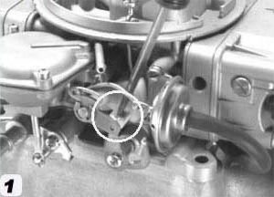
To set the fast idle speed: Insert a medium flat blade screwdriver into the slotted tang on the fast idle lever as shown in the white circle in picture #1 below. Twist clockwise to bend the tang towards the front of the car to increase fast idle RPM. Twist counter-clockwise to bend the tang back towards the rear of the car to lower fast idle RPM.
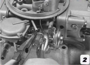
To set the choke blade angle, bend the small wire link between the choke pull-off and the choke fast idle cam cage as seen in picture #2 below. Shortening the link by bending the ends closer together will cause the choke pull-off to pull the choke blade open farther for a leaner idle mixture, and lengthening the link by bending the ends further apart from each other will open it less for a richer idle mixture.
To adjust the curb idle speed, the engine will need to be at full operating temperature and the choke will need to be completely open and dis-engaged. To verify this, make sure the fast idle lever is not resting on any of the steps on the plastic fast idle cam.
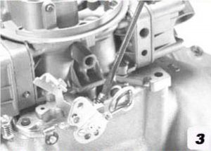
To raise the curb idle speed, turn the screw clockwise as shown in Pic. 3 above. To lower the curb idle speed, turn the screw counter-clockwise.
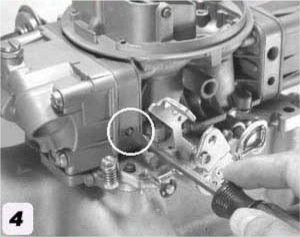
To adjust the idle mixture trim screws, the engine will need to be at full operating temperature and at curb idle speed. Begin by slowly turning the mixture screw (as shown in picture #4 on the following page) in (clockwise) no more than 1/8 of a turn at a time until the engine stumbles, then backing out again just until the stumble clears up. Then turn the screw back out an additional 1/8 turn. Repeat this process on both mixture screws (one on each side of the carburetor).
If you experience difficulty in getting the trim screws adjusted, turn the engine off completely and re-establish a baseline setting by gently turning the mixture screws in (clockwise) until you feel them lightly bottom out.
*DO NOT FORCE THEM IN ANY FURTHER THAN THIS*
Then turn each screw out (counter-clockwise) 1 & ¼ turns. This is your baseline setting. Repeat the process until a stable, smooth idle is obtained.
*Note* You may find the screws will be anywhere from 1/2 to 1 & 3/4 turns out once you are finished with the adjustments. This is considered the normal adjustment “window”. If smooth operation can not be achieved within this range, please contact me for further instructions.
To adjust float settings (carburetors with externally adjustable floats only);
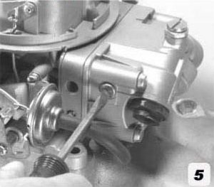
Begin by removing the float bowl sight plugs located on the sides of both front and rear float bowls as indicated picture #5 below. You may wish to place rags under them as some fuel may spill when the plugs are removed. Make sure the sight plug gaskets do not fall or get lost when the plugs are removed.
*AGAIN, HAVE AN APPROPRIATE FIRE EXTINGUISHER NEARBY WHEN PERFORMING THESE ADJUSTMENTS*
Start the engine and allow to idle.
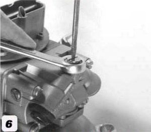
Place a 5/8” wrench (box end preferred) over the float adjuster nut, and using a large flat blade screwdriver, barely loosen the set screw on top as shown in picture #6. *NOTE* Some fuel will likely escape from below the lock screw & nut–this is normal, do not be alarmed, but keep the lock screw just barely loose from the nut to minimize leakage.
Proper float adjustment will be confirmed when the fuel level is slightly below the site plug hole (as pictured in picture #5 on the previous page), and gently rocking the car side to side allows the fuel to barely spill out of the site plug hole. To raise the float level, turn the adjuster nut counter-clockwise. To lower the fuel level, turn the adjuster nut clockwise.
Once the proper float level has been set, tighten the set screw (as seen in picture #6 below) making sure the adjuster nut does not move in the process.
*DO NOT OVER-TIGHTEN THE SET SCREW. DOING SO CAN DAMAGE THE THREADS IN THE FLOAT BOWL/ DO NOT TRY TO “TWEAK” THE SETTING BY TURNING THE ADJUSTER NUT WITHOUT LOOSENING THE SET SCREW FIRST. DOING SO WILL RESULT IN DAMAGE TO THE FLOAT BOWL AND POSSIBLE FUEL LEAKS AND A POTENTIAL FOR FIRE.*
Perform this procedure on the front float bowl first, then repeat the procedure on the rear float bowl. Be sure to re-install both the float bowl sight plugs with their respective gaskets once the float levels have been set.
A carburetor’s biggest enemy is dirt! A clean supply of fuel is a must for proper performance. 99{e8a31ad70eb76b9d1736af28c4c10c5ce60babf18dd7728d2fa05ac44ba5f2cd} of the carburetors returned to me with complaints have fallen victim to a dirty fuel supply.
Most OEM carburetors will have a sintered bronze filter element installed in the float bowl behind each inlet fitting. *DO NOT REMOVE THESE!* Contrary to popular myth, they do not pose any significant flow restriction provided they are kept clean. If you suspect they are in need of replacement, do NOT simply remove and discard them, be sure to install new replacements.See the accompanying tech article on how to service your fuel filter elements.
A clean air filter element is equally important. Some of the passages on a carburetor that are exposed to the air inlet system are as small as .020” (that’s twenty thousands of an inch). It doesn’t take much dirt to plug one up.
These are basic adjustments you WILL be required to perform once you have your carburetor installed. They will be “base lined” when you receive the carburetor, but every application is slightly different and will require further refinement to suit your particular vehicle. If you have any questions or concerns, please don’t hesitate to contact me.